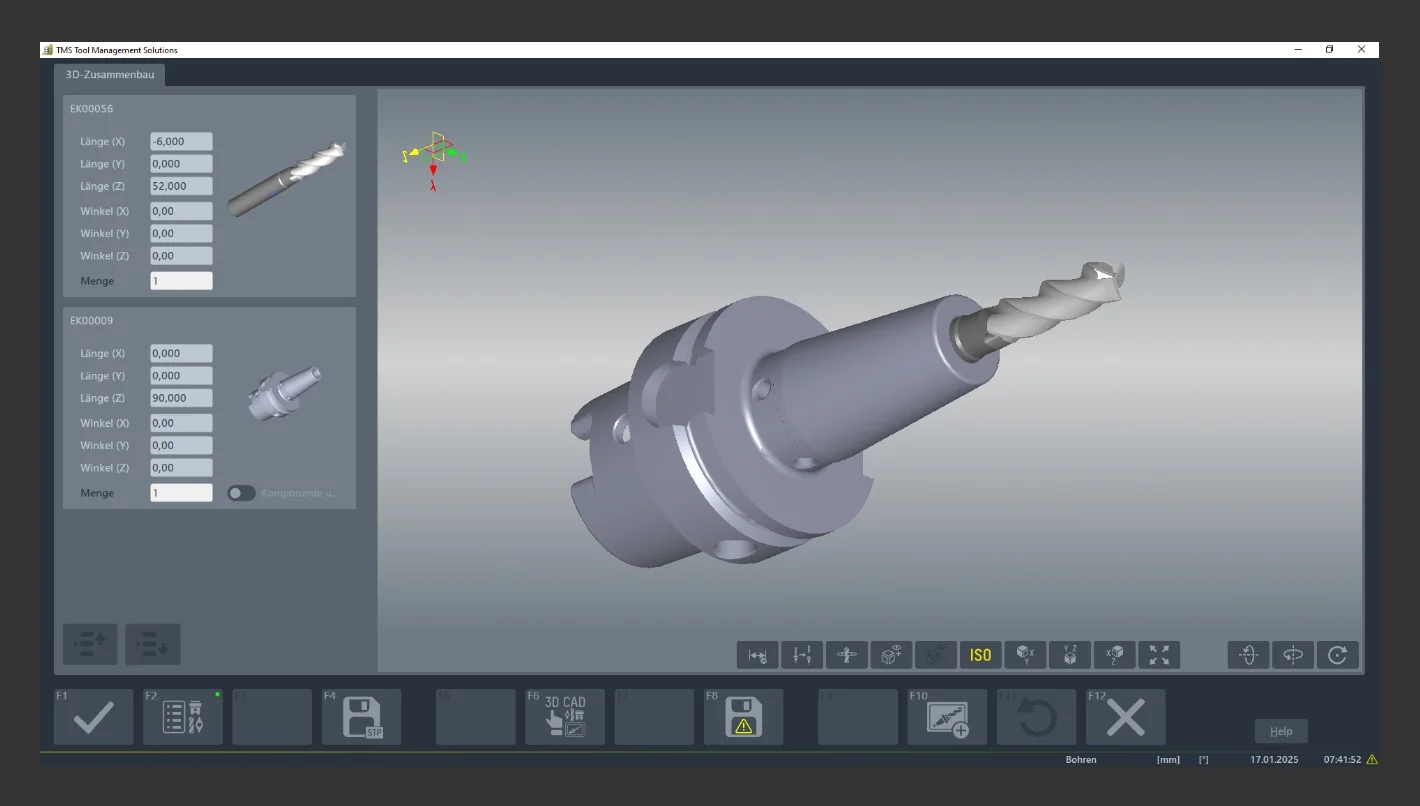
Complete tools consist of several components—usually a tool holder, a tool carrier, and cutting elements. The data for these components is typically available in the ZOLLER TMS Tool Management Solutions tool and tool data management system as master data as well as 2D and 3D graphics. Using the graphic assembly function, complete tools can thus be quickly, simply, and reliably generated virtually, as well as created and saved as a data record.
Combine Only Plausible Components
To do this, work planners first select components from lists in the ZOLLER TMS Tool Management Solutions software. A wide range of freely selectable search criteria makes this very simple. For example, components can be selected based on symbolic graphics according to machining processes, tool holder sizes and executions (corresponding to ISO and DIN), or according to the required cutting circle diameters for cutting edges.
The additional “interface coding” function proves especially advantageous for fast and reliable selection. It automatically inspects the interfaces of the selected components. When components are arranged in accordance with DIN standards, the individual-component library automatically filters out incompatible elements. This ensures, for example, that tools with 10-mm-diameter Weldon shafts can only be combined with holders of the same dimensions and executions. This ensures maximum process reliability when assembling complete tooling.
After a suitable selection of individual components, a 2D graphic including dimensions is automatically generated. This includes, among other things, the lengths over which a shaft is to be shrink-fitted or screwed in. In addition, the 2D graphic shows the assumed zero point of the complete tool, which is required for presetting & measuring in the NC program.
View Photorealistic Models
With a keystroke, solid models of the complete tools can be generated. The generated 3D models are then saved in the ZOLLER z».«One database. These graphics serve as the basis for programming in the respective CAD/CAM systems.
A wide variety of CAD/CAM systems can import this data using a ZOLLER interface. This means that manufacturing companies are not restricted by their selection of CAM systems. They can also exchange their CAD/CAM software simply and without any problems.
Clear Assignment
To enable work planners to quickly and easily identify and determine the components required for assembly, the graphic assembly view in the 3D models of the complete tools displays the components in different colors. When the graphics are clicked, the software module highlights the corresponding components in the lists displayed alongside them. This allows assembly specialists to reliably identify these components and assemble them with reliable process reliability.
Custom Expansion
Many manufacturing facilities use custom-constructed tools. These, too, can be imported into the ZOLLER TMS Tool Management Solutions software. To do so, only generate STEP-format files in the 3D CAD system and save them to the ZOLLER »z.One« database. Of course, the graphic assembly function enables the assembly of complete tool sets of any type for different machining processes. This allows grinding wheel sets and non-radially symmetric turning tools to be automatically designed from selected components using the same procedures as for milling and drilling tools. For components constructed and dimensioned strictly according to DIN standards, the system automatically checks whether the interfaces of the components fit together to one another and whether an assembly is feasible. Thus, the graphic assembly feature ensures that manufacturing facilities can work especially efficiently and reliably when assembling complete tools. This shortens lead times, increases flexibility, and reduces costs.




 Back to overview
