


Safely and efficiently to your destination
With the ZOLLER »redomatic«, shrink tools are quickly ready for use. The »pilot 4.0« image processing software, the auxiliary unit and the permanent monitoring of the work steps facilitate fast and reliable work.
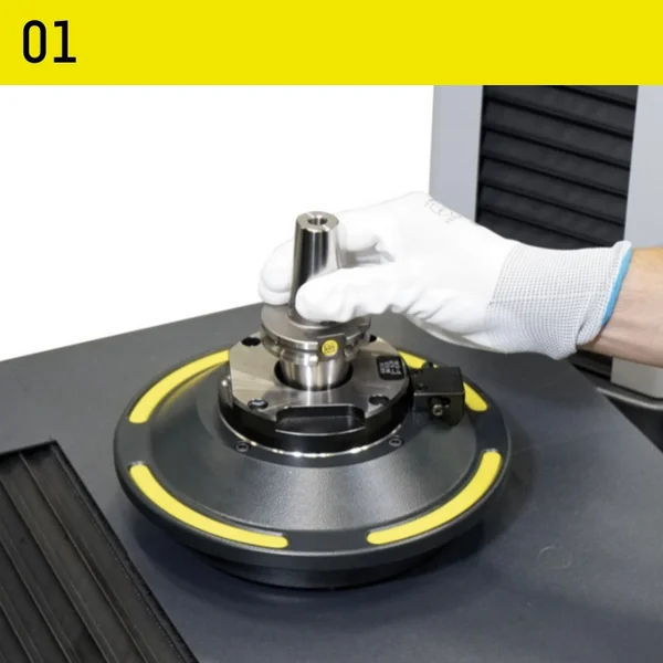
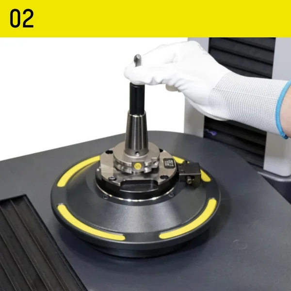
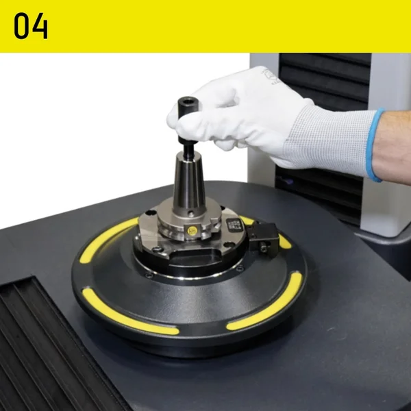
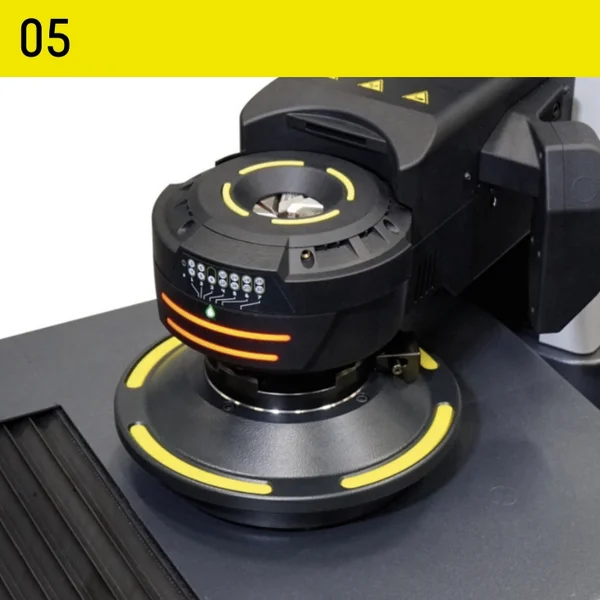
The »redomatic« technology ensures the shortest possible process times. Even inexperienced operators can achieve this after just a short training period. All components have their fixed position on the auxiliary unit. The »pilot 4.0« image processing software guides the operator through all work steps and controls many processes fully automatically. For each work step, the software names the component that is required and shows on the screen where the component is located on the auxiliary unit. »redomatic« is the solution for setting, measuring and shrinking tools to the exact length required.
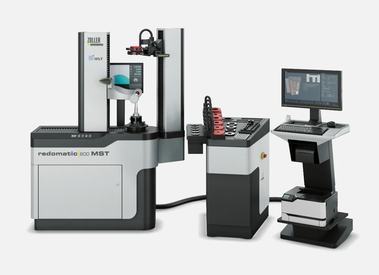
»redomatic 600« MST
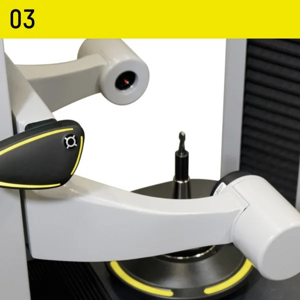
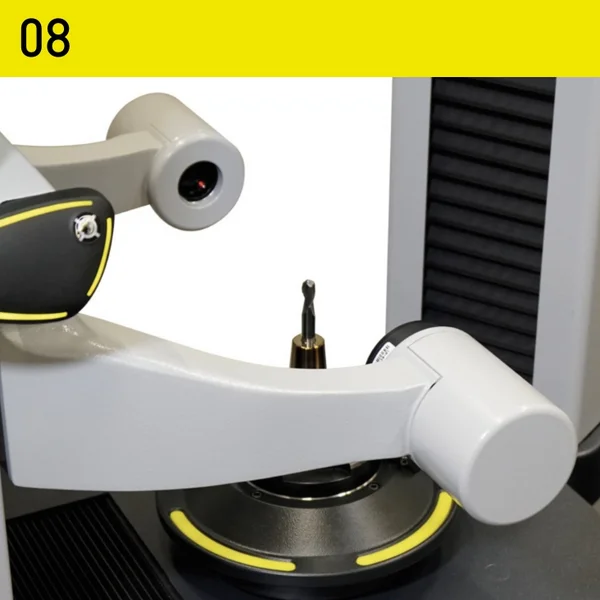
Automated shrinking of tools to an accuracy of 10 μm
With a »redomatic 600« MST from ZOLLER, you can make optimum use of the advantages of your MST tool holders and thus increase the efficiency of your production.
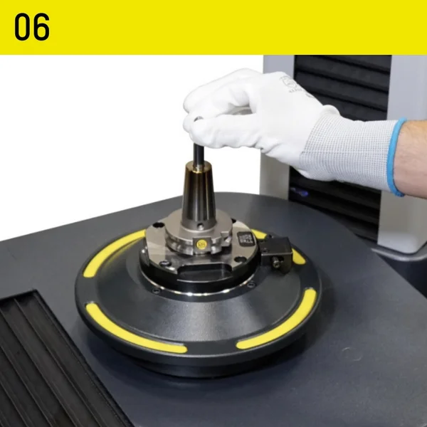
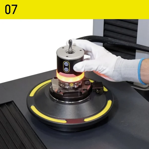
Because with »redomatic 600« MST you can be sure that the tool lengths are always set correctly. The shrinking process developed by ZOLLER with the »masterPiece« setting adapter is both quick and easy. The perfect interplay between mechanics, pneumatics, electronics and software as well as the continuous parameter monitoring and automatic measuring sequences guarantee you maximum process reliability.
»pilot 4.0« is the extensive and comprehensive software solution for all ZOLLER presetting and measuring machines. The intuitive graphical user interface guides users quickly and reliably to precise measurement results. This makes »pilot 4.0« so easy to use that even complex measuring tasks can be completed immediately. At the same time, the software is so comprehensive in its functionality that there is a solution for every requirement. It is not for nothing that »pilot 4.0« is considered the world's unrivaled benchmark for tool setting, measurement and testing.
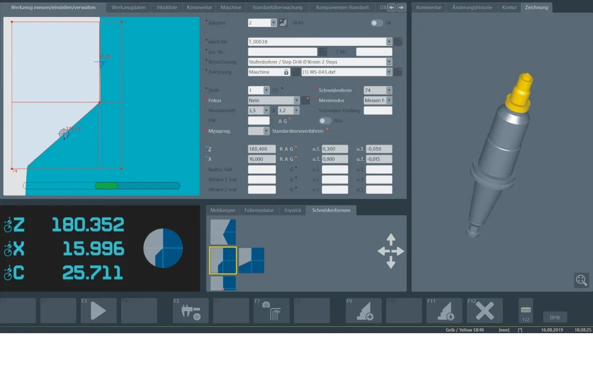
Tool-specific information
Adapter management
- Tool designation for individual identification
- Target values with tolerances
Cutting edge shapes
Automatically recognized cutting edge shapes
Function buttons
With self-explanatory icons
Current camera image of the cutting edge
- Dynamic crosshairs
- Angle indication with selectable reference axis
Current position information
- Current position information of the axes
- Currently active cutting edge shape
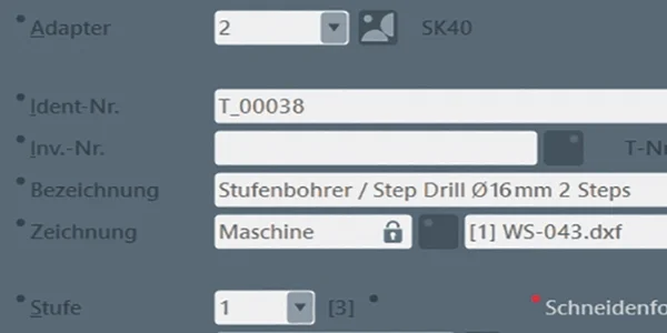
- Tool designation for individual identification
- Target values with tolerances
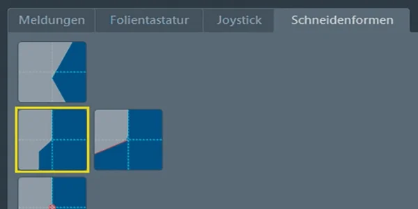
Automatically recognized cutting edge shapes

With self-explanatory icons

- Dynamic crosshairs
- Angle indication with selectable reference axis
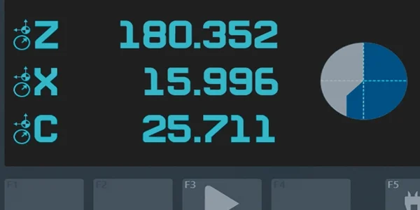
- Current position information of the axes
- Currently active cutting edge shape

